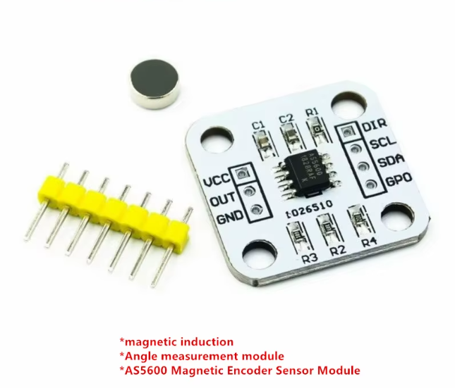
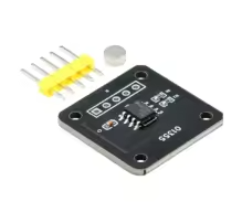
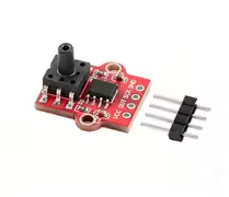
AS5600 Magnetic Encoder Angle Measurement Sensor Module
= 12Bit HighPrecision Non-Contact Magnetic Position Sensor =
The AS5600 is a programmable 12bit highresolution magnetic rotary position sensor that provides non-contact absolute angle measurement . It detects the position of a diametrically magnetized magnet placed above the IC, offering a reliable alternative to traditional potentiometers and optical encoders.
12Bit Resolution 4096 positions per revolution for high-precision angle tracking
Contactless Measurement - No mechanical wear for excellent durability and reliability
Operating voltage: 3.3V or 5V with I2C address 0x36
Keep magnet within 0.5mm to 3mm vertical distance for optimal detection
Ensure magnet is properly aligned with the sensor center and is sufficiently strong
= Technical Specifications =
| Parameter | Value |
|---|
| Resolution | 12-bit (4096 positions per revolution) |
| Accuracy | 0.1° precision with typical ±0.4° accuracy |
| Interface | I2C (address 0x36), PWM, Analog output |
| Supply Voltage | 3.3V / 5V |
| Operating Temp | -40°C to +125°C |
= Key Features =
NonContact Sensing No mechanical wear, friction, or rotation angle limitation
Flexible Output Modes - Supports I2C, PWM, and analog voltage output
Configurable Range - Maximum angle programmable from 18° up to 360°
Automatic Magnet Detection Builtin gain control and diagnostics for magnet placement
Direction Selection - DIR pin configures clockwise or counterclockwise output
== Applications ==
- Closed-loop motor control and feedback systems
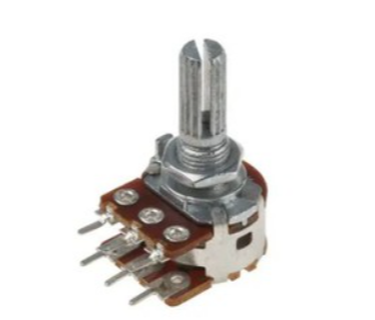
- Contactless potentiometer and knob replacements
- Robot arm and joint angle measurement
- Industrial machine tool positioning
- Gimbal and tripod head position tracking
NonContact Design Ideal for harsh environments with no mechanical wear
4096 Positions - Provides smooth, accurate angle measurement for critical applications
√ Supports Arduino, ESP32, Raspberry Pi with multiple libraries
√ Onboard voltage regulator for 3.3V/5V compatibility
√ STEMMA QT connector for plugandplay I2C wiring
= Connection Guide =
Basic I2C wiring to Arduino:
- VIN: 5V (or 3.3V) power
- GND: Ground
- SDA: I2C data line
- SCL: I2C clock line
- OUT: Optional analog/PWM output
Use I2C address 0x36 by default not userconfigurable
For analog output, connect OUT pin to ADC input 0V to VDD corresponds to 0360°
DIR pin must be tied to GND or VDD - leave floating causes erratic behavior
I2C lines require pull-up resistors (10kΩ onboard on many modules)
= Troubleshooting =
No angle data:
- Verify magnet is detected and within correct field range
- Check I2C connections and pull-up resistors
- Ensure DIR pin is properly tied (GND or VDD)
Inaccurate readings:
- Align magnet with sensor center, vertical distance 0.5-3mm
- Use a rare earth magnet (e.g., neodymium) for reliable field strength
- Check magnet is diametrically magnetized, not axially