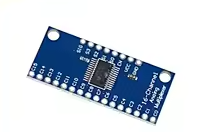
74HC4067 16-Channel Analog Digital Multiplexer Breakout Board
= CD74HC4067 Module for Arduino DIY Projects =
This 74HC4067 multiplexer board expands 16 analog or digital input channels using just 4 control pins. Ideal for Arduino projects requiring multiple sensor inputs with minimal GPIO usage.
16to1 Multiplexing - Reads 16 inputs with only 4 control pins
Low OnResistance 60Ω typical for reliable analog readings
Connect common pin to Arduino analog input
Use digital pins for selection lines
Do not exceed 6V supply voltage
= Technical Specifications =
| Parameter | Value |
|---|
| IC Type | 74HC4067 / CD74HC4067 |
| Channels | 16 inputs/outputs |
| Supply Voltage | 2V to 6V |
| Control Pins | 4 (S0-S3) |
| Enable Pin | Active low (EN) |
| On-Resistance | 60Ω typical |
| Bandwidth | 50MHz |
= Key Features =
Expands I/O Capacity - 16 channels from 4 control pins
Bidirectional - Works for analog or digital signals
Breakout Board Design - Easy connection points
Low Power Consumption - Minimal current draw
Wide Voltage Range - 2V to 6V operation
== Applications ==
- Multi-sensor monitoring
- Analog signal multiplexing
- LED matrix control
- Audio signal routing
- Data acquisition systems
- Test equipment expansion
GPIO Saver - Saves microcontroller pins
Reliable Switching - Low resistance for accuracy
√ Labeled pin headers
√ 16 individual channel pins
√ Common pin for connection
= Connection Guide =
Control pins:
- S0, S1, S2, S3: Channel select
- EN: Enable (low to activate)
- COMMON: Shared input/output
- VCC: 2-6V power
- GND: Ground
Channel selection:
- Binary input on S0-S3 selects channel
- 0000 = Channel 0, 1111 = Channel 15
- Enable low to activate
Connect COMMON to Arduino analog pin
Use binary math for channel selection
Enable pin must be low to operate
Connect VCC before applying signals
= Arduino Usage Example =
Select channel 5:
- S0 high (1), S1 low (0), S2 high (1), S3 low (0)
- Binary 0101 = Channel 5
- Enable low to activate connection
For analog input:
- Connect COMMON to Arduino analog pin
- Read selected channel using analogRead()
- Switch channels to scan multiple sensors
Simple Control - DigitalWrite for selection
Quick Scanning - Read all 16 channels rapidly
Compatible with analog and digital signals
Works with 5V and 3.3V logic
√ Channel pins labeled for easy identification
√ Enables multiple sensor projects
√ Great for beginners and experts
= Channel Selection Table =
Binary S3S2S1-S0 selects channel:
- 0000 = Ch0, 0001 = Ch1
- 0010 = Ch2, 0011 = Ch3
- 0100 = Ch4, 0101 = Ch5
- 0110 = Ch6, 0111 = Ch7
- 1000 = Ch8, 1001 = Ch9
- 1010 = Ch10, 1011 = Ch11
- 1100 = Ch12, 1101 = Ch13
- 1110 = Ch14, 1111 = Ch15
Set EN pin LOW before selecting channels
Use shift registers for more expandability
Do not leave EN pin floating
Use capacitor for noise filtering
= Troubleshooting =
Wrong channel selected:
- Check binary pin states
- Verify S0-S3 connections
- Avoid floating control pins
Inconsistent readings:
- Add capacitor on analog input
- Use averaging for noisy signals
- Avoid long unshielded wires