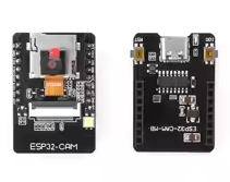
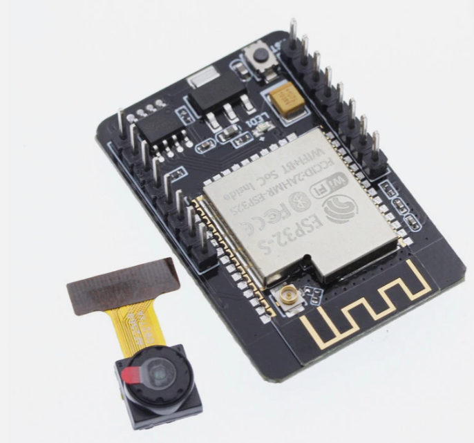
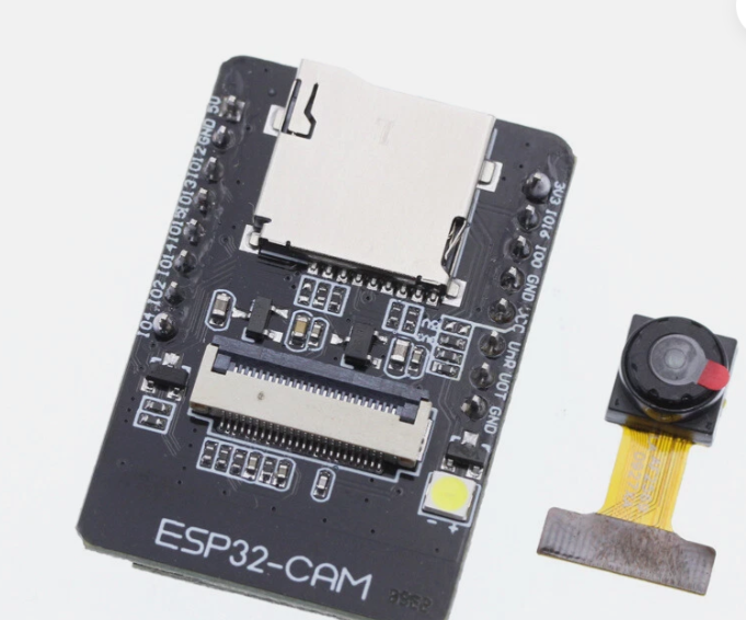
ESP32-CAM WiFi Bluetooth Camera Development Board
= Compact IoT Module for Wireless Surveillance and Vision Projects =
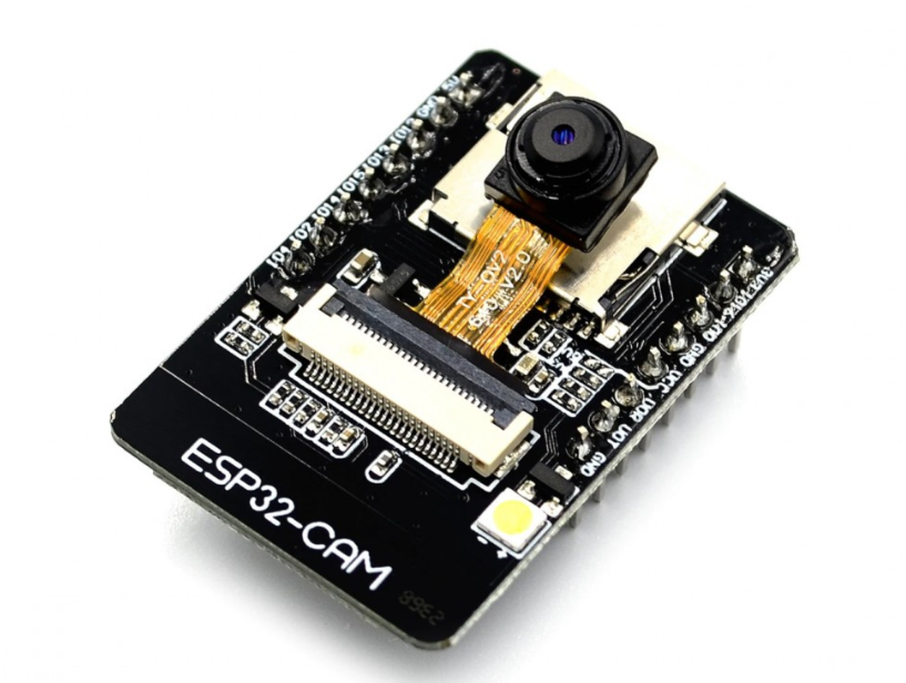
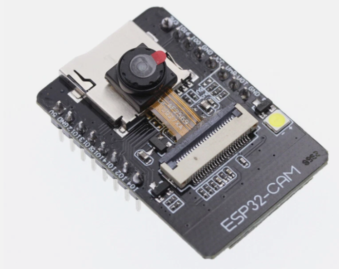
The ESP32CAM is a powerful, lowcost development board that combines a dualcore ESP32 processor with an OV2640 camera sensor, WiFi, and Bluetooth in a tiny form factor (27x40.5x4.5mm) . It is an ideal solution for wireless monitoring, smart home devices, industrial control, and AI vision applications like face detection and QR recognition .
DualCore Processor & Camera Xtensa LX6 CPU up to 240MHz with 2MP OV2640 camera
Builtin WiFi, Bluetooth & Storage - 802.11 b/g/n, BLE 4.2, and MicroSD card support
Power requirement is 5V DC at a minimum of 2A; insufficient power causes image distortion
For programming without an external FTDI adapter, use the ESP32CAMMB base board with USB connectivity
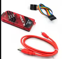
The ESP32CAM has no builtin USB port; use a USBtoSerial programmer (e.g., FTDI) connected to the UART pins or the MB base board for uploading code
= Technical Specifications =
| Parameter | Value |
|---|
| -- | -- |
| Processor | ESP32S DualCore Xtensa LX6 |
| Clock Speed | Up to 240MHz |
| Flash Memory | 32Mbit (4MB) default |
| PSRAM | 4MB or 8MB external (varies) |
| Wi-Fi | 802.11 b/g/n/e/i (2.4GHz) |
| Bluetooth | 4.2 BR/EDR and BLE |
| Camera Sensor | OV2640 (2MP) |
| Image Output | JPEG (OV2640), BMP, GRAYSCALE |
| IO Pins | 9 (shared with camera interface) |
| MicroSD Card Support | Up to 4GB |
| Power Supply | 5V DC (4.75-5.25V) |
Key Features
DualCore Processing 600 DMIPS computing power for complex vision tasks
Integrated Wireless WiFi and Bluetooth for remote streaming and control
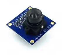
OV2640 Camera - Captures images up to 2MP and supports JPEG output for efficient transmission
MicroSD Card Slot - Local storage for captured images and files
Multiple Sleep Modes Deep sleep current as low as 6mA for lowpower operation
Flash Lamp Builtin LED for low-light conditions
== Applications ==
- Wireless surveillance and home security cameras
- Remote monitoring for smart agriculture and industrial inspection
- Face detection and recognition projects
- QR code and wireless identification systems
- DIY robotics vision modules
Affordable Vision Platform One of the most costeffective solutions for IoT and camera projects
Versatile Connectivity WiFi, Bluetooth, and GPIOs for flexible project integration
√ Works with Arduino IDE, ESP-IDF, and MicroPython
√ External antenna support and PCB antenna option available
√ Compact size ideal for portable and space-constrained projects
= Key Pinout Information =
The ESP32-CAM has three power pins (5V, 3.3V) and three GND pins . The UART pins (GPIO1 = TX, GPIO3 = RX) are used for programming, and for uploading code, GPIO0 must be connected to GND to enter flashing mode .
The MicroSD card slot uses the following pins internally :
- GPIO14: CLK, GPIO15: CMD, GPIO2: Data 0, GPIO4: Data 1, GPIO12: Data 2, GPIO13: Data 3.
For programming, use a USBtoSerial adapter or the ESP32CAMMB base board (which includes a USB port for simplified operation) .
The GPIO4 pin is also connected to the onboard LED—consider this when using the MicroSD card or controlling external devices.
Do not pull GPIO0 high or low during normal operation, as it is connected to the camera XCLK signal and must be left floating .
The power supply must be capable of delivering at least 2A; otherwise, the camera image may have horizontal colored lines or water ripples .
Troubleshooting
No image or distorted image:
- Ensure power supply provides 5V 2A minimum (not just 1A)
- Pull GPIO32 pin LOW during camera operation
- Check camera module is properly seated in the connector
ESP32-CAM not detected for programming:
- Install CH340/CP2104 USB driver for the programmer
- Use a datacapable USB cable (not chargeonly)
- Connect GPIO0 to GND before powering on to enter flashing mode
Wi-Fi connection issues:

- Connect to a 2.4GHz network (not 5GHz)
- Verify SSID and password in the code
- Check signal strength and antenna connection