I2C LCD Adapter for 1602 and 2004 Displays
= Serial Interface Module for Arduino LCD Projects =
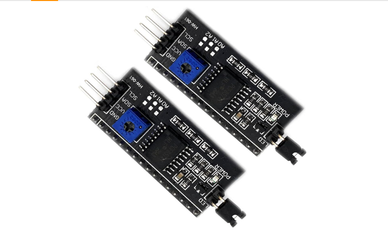
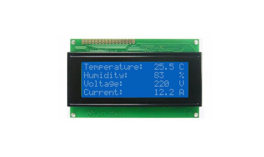
The I2C LCD adapter is a serial interface module designed to simplify wiring for 1602 (16x2) and 2004 (20x4) character LCD displays . Often called an "LCD backpack," it converts the standard 16pin parallel connection into a simple 4wire I2C interface (VCC, GND, SDA, SCL), saving valuable GPIO pins on your Arduino or other microcontroller .
Saves I/O Pins Uses only 2 pins for data (SDA, SCL) instead of 610 pins
Onboard Contrast Adjustment Builtin potentiometer for fine-tuning display visibility
Operating voltage is 5V DC, with 3.3V compatible versions available
Default I2C address is 0x27, but can be adjusted to 0x20-0x3F using solder jumpers
Check your LCD's voltage compatibility before connecting
= Technical Specifications =
| Parameter | Value |
|---|
| Interface | I2C (SDA, SCL) |
| Supply Voltage | 5V (3.3V-5V on some models) |
| I2C Address | 0x27 (default, adjustable) |
| Chip | PCF8574T or AiP31068 |
| Adjustments | Contrast potentiometer, Backlight jumper |
= Key Features =
+Simple Wiring - Only 4 connections needed (VCC, GND, SDA, SCL)
+Compatibility - Works with 1602 (16x2) and 2004 (20x4) character LCDs
+Backlight Control - Jumper to enable/disable backlight
+Library Support - Compatible with LiquidCrystal_I2C and similar libraries
== Applications ==
- Arduino and Raspberry Pi projects
- Displaying sensor data and status messages
- Menu interfaces for embedded systems
- Compact data logging displays
- Projects where pins are limited (e.g., with sensors/SD cards)
Saves GPIO Pins - Ideal for projects with many sensors or actuators
Easy Integration - One of the most common LCD methods for Arduino
√ Multiple addresses for daisy-chaining up to 6+ displays
√ Solder pads (A0/A1/A2) for address selection
√ Fast 100kHz I2C communication
= Connection Guide =
| Module Pin | Arduino UNO | ESP32 |
|---|
| VCC | 5V | 3.3V or 5V |
| GND | GND | GND |
| SDA | A4 | GPIO21 |
| SCL | A5 | GPIO22 |
Use I2C scanner sketch to find the address of your module if 0x27 doesn't work
Adjust the blue potentiometer to set contrast
Only use 3.3V if your module specifically supports it
Troubleshooting
No display:
- Adjust the contrast potentiometer
- Verify I2C address (try 0x27 or 0x3F)
- Check wiring (SDA/SCL swapped?)
Garbled characters:
- Check baud rate and initialization in code
- Verify backlight jumper is connected
- Try a different I2C address