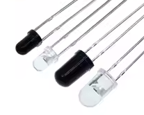
5mm 940nm Infrared Emitter and IR Receiver LED 301A for Arduino
= Reliable IR Pair for Remote Control and Sensor Projects =
This 301A pair set includes infrared emitting diodes and phototransistor receivers, both matched to the 940nm wavelength for optimal signal transmission. With a 5mm diameter package, they are ideal for DIY remote control, obstacle detection, and automated systems using Arduino or other microcontrollers .
Matched Pair - Both emitter and receiver tuned for 940nm operation
Reliable Signal Transmission Up to 78 meters range
Forward voltage: 1.2V to 1.5V (emitter); Receiver output: TTL level
Use a current-limiting resistor (100Ω to 220Ω) in series with the emitter
The receiver responds only to pulsed/modulated signals (e.g., 38kHz carrier), not a constant DC beam
= Technical Specifications =
| Parameter | Emitter (LED) | Receiver (Diode) |
|---|
| Wavelength | 940nm | 940nm |
| Forward Voltage | 1.2V - 1.5V | N/A |
| Continuous Current | 20mA - 100mA | N/A |
| Peak Pulse Current | 1000mA | N/A |
| Receiving Angle | N/A | ~40 degrees |
| Material | 5mm diameter | 5mm diameter |
= Key Features =
Matched Spectrum - Emitter and receiver are tuned to 940nm, ensuring maximum signal strength
Common 5mm Package - Standard footprint fits breadboards and PCBs easily
Phototransistor Receiver Outputs a TTLcompatible signal, ideal for connecting directly to a microcontroller pin with a pull-up resistor
Small Size - Easy to position for obstacle detection modules
== Applications ==
- DIY remote control for TV, fan, or robot
- Linefollowing or obstacleavoidance robot sensor
- Contactless RPM measurement (tachometer)
- Security system beam break detection
- Educational electronics projects
Most Common Standard - 940nm is the widely used wavelength for consumer IR
Easy to Use - Compatible with IRremote library for rapid development
√ Through-hole design compatible with Arduino sensor shields
√ Pack of 10 pairs available for multiple projects
= Connection Guide =
Wiring the Emitter (LED):
- Connect the anode (longer leg) to a digital output pin via a ~220Ω resistor.
- Connect the cathode (shorter leg) to GND.
- Send a modulated signal (e.g., using the IRremote library) for effective communication .
Wiring the Receiver (Phototransistor):
- Connect the collector (often the longer leg) to VCC (3.3V or 5V) through a 10kΩ pull-up resistor .
- Connect the emitter (shorter leg) directly to GND.
- Read the output signal from the connection point between the receiver and the pull-up resistor using a digital input pin .
For remote control, use the IRremote library to simplify modulation
For simple detection (e.g., object presence), test for a falling edge when the beam is interrupted
Do not exceed 5V reverse voltage on the receiver
The receiver's output is active low (LOW when receiving a matching 38kHz signal)
= Troubleshooting =
Signal not received:
- Ensure the emitter is driven by a modulated signal (38kHz), not a constant DC voltage
- Verify the receiver's output pin is pulled up (internally or externally)
- Avoid direct exposure to sunlight or strong incandescent light
Short range:
- Ensure the emitter current is sufficient (up to 100mA continuous)
- Align the emitter directly with the receiver's field of view (~40 degrees)
- Remove physical obstructions
 2.png "Buy MQ-5 Gas Sensor Module for KSH 600 – HIMA TRONICS Mombasa – Quality electronics in Mombasa, Kenya")