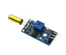
SW-520D Digital Tilt Sensor Module – High Sensitivity Inclination Detection for Arduino, DIY Alarm, Smart Device
KSH 200.00
Out of Stock
The SW-520D tilt sensor module detects angular changes and vibrations using a metal ball mechanism. It outputs a digital logic signal (HIGH/LOW) when tilted beyond a threshold, making it perfect for alarm systems, smart devices, and robotic applications.
| Parameter | Value |
|---|---|
| Sensor Type | Roller-ball tilt/vibration switch |
| Operating Voltage | 3.3V to 12V DC |
| Current Consumption | 15mA typical |
| Output Form | Digital switch output (0 and 1) |
| Comparator IC | LM393 |
| Board Size | 37 x 14mm |
NonMercury Design Safe and environmentally friendly alternative to mercury switches
LM393 Comparator - Clean, stable output signal with strong drive capability
Adjustable Sensitivity Onboard potentiometer for finetuning trigger angles
Visual Indicators - Power and status LEDs for immediate feedback
Easy Mounting - M3 mounting hole for secure attachment to objects
Sealed Construction Dustproof and moistureresistant design
√ M3 mounting hole for easy installation
√ 3-pin interface (VCC, GND, DO) for simple wiring
√ Compatible with Arduino, ESP8266, ESP32, and 8051 MCUs
Module pinout:
Wiring to Arduino:
Note: Analog output (AO) is typically not used on this module
No output signal:
Module not responding to tilt: