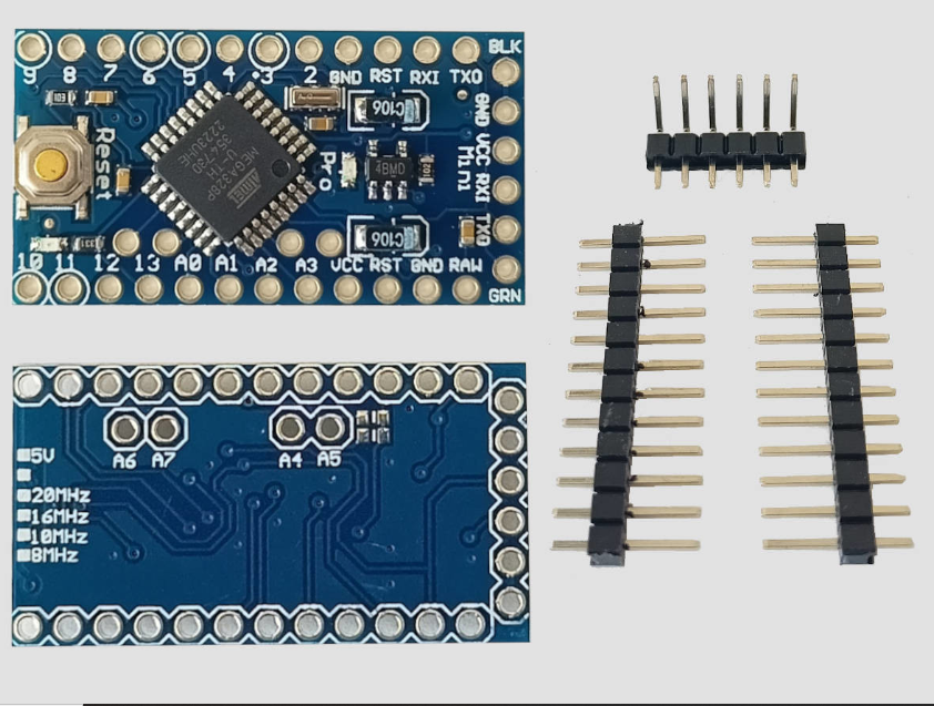
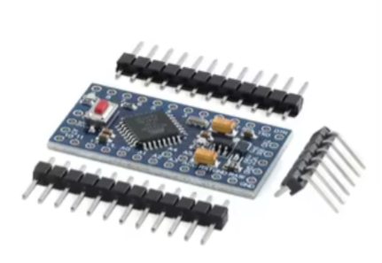
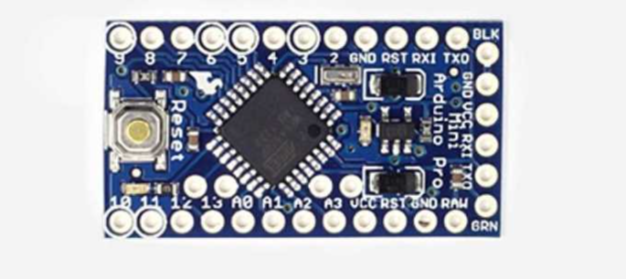
Arduino Pro Mini Development Board
= Compact, Low-Cost Board for Embedded Projects =
The Arduino Pro Mini is a compact, lowcost microcontroller board based on the ATmega328P, designed for users who want to embed the board in their projects permanently . It comes with the minimum components, no onboard USB or presoldered headers, to maximize flexibility and keep the cost down . This makes it a perfect choice for spaceconstrained and cost-sensitive applications.
Compact & LowCost Smallest Arduino board for permanent installation
ATmega328P Core - 32KB Flash, 2KB SRAM, 1KB EEPROM
The board comes in two versions: 5V/16MHz and 3.3V/8MHz .
Requires an external USBtoTTL serial adapter (e.g., FTDI) for programming .
I/O pins operate at 3.3V or 5V logic based on the version - check your model before connecting external components .
= Technical Specifications =
| Parameter | 5V Version | 3.3V Version |
|---|
| -- | -- | -- |
| Microcontroller | ATmega328P | ATmega328P |
| Operating Voltage | 5V | 3.3V |
| Clock Speed | 16 MHz | 8 MHz |
| Digital I/O Pins | 14 (6 PWM) | 14 (6 PWM) |
| Analog Input Pins | 6-8 (depends on board) | 6-8 (depends on board) |
| Flash Memory | 32 KB (2 KB bootloader) | 32 KB (2 KB bootloader) |
| SRAM | 2 KB | 2 KB |
| EEPROM | 1 KB | 1 KB |
| Dimensions | 18 x 33 mm | 18 x 33 mm |
= Key Features =
Compact Size Excellent for wearable or spaceconstrained devices
Low Cost Minimal components make it affordable for oneoff projects
Fully ArduinoCompatible Uses standard Arduino IDE
RAW Pin Power Input Accepts 512V (5V board) or 3.3-12V (3.3V board) unregulated supply
== Applications ==
- Wearable electronics and portable devices
- Permanent installations and embedded projects
- Battery-powered applications (3.3V version recommended)
- Sensor data logging and monitoring
Ideal for Embedded Projects - Designed to be soldered permanently into a circuit
Choice of Voltage - 5V for common components, 3.3V for low power and modern sensors
√ Can be powered via RAW (5-12V) or VCC (regulated) pins
√ Programming is done via 6-pin FTDI header
√ Reset button included on most models
= Programming and Connection Guide =
Programming Setup :
- Connect an FTDI programmer to the 6-pin header (RXI, TXO, VCC, GND, DTR, BLK).
- In Arduino IDE, select the correct board variant: "Arduino Pro or Pro Mini (3.3V, 8 MHz)" or "Arduino Pro or Pro Mini (5V, 16 MHz)".
- Use external power on RAW or VCC when programming.
Power Sources :
- RAW: Unregulated input (512V for 5V board, 3.312V for 3.3V board) through onboard regulator.
- VCC: Regulated power (exactly 5V or 3.3V), bypasses the regulator.
- USB via FTDI: Can power the board through the FTDI programmer.
To enable auto-reset with FTDI on Windows, enable "Set RTS on Close" in the device's port settings .
For 3.3V version, the board is popular for battery projects and interfacing with 3.3V sensors .
Do not apply >12V on RAW pin, ensure correct voltage for your board variant .
= Troubleshooting =
No response after upload:
- Ensure the correct board (5V vs 3.3V) is selected in the IDE .
- Check FTDI adapter connections (DTR must be connected for auto-reset) .
- Verify external power is sufficient if powering through the RAW pin.
Board not powered:
- Verify the FTDI adapter is providing power or external power is connected.
- Check for correct connection: VCC to VCC, GND to GND .
- Avoid powering the board from both USB and RAW simultaneously.
Upload errors:
- Ensure the correct COM port is selected.
- Try pressing the reset button just before upload begins .
- For clones, an older bootloader may require selecting "ATmega328P (Old Bootloader)" .