ESP32-C3 SuperMini V2.0 Red Board
= UltraCompact RISCV Development Board with USB-C =
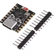
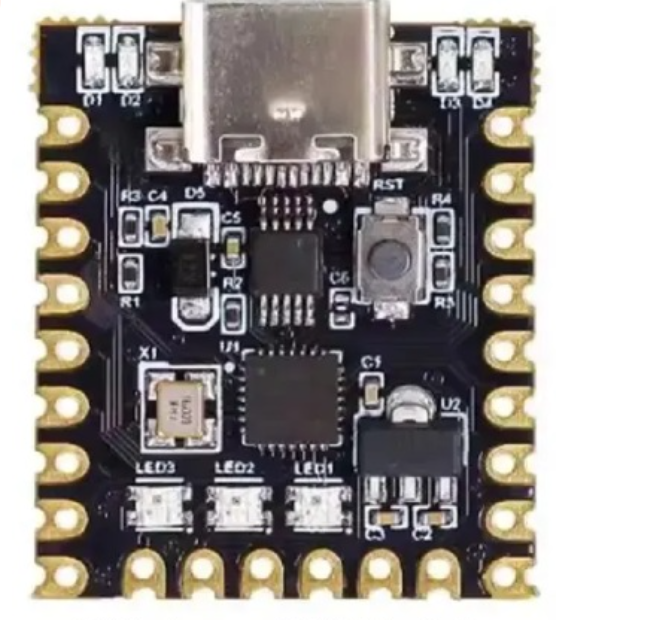
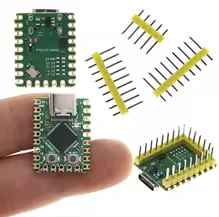
The ESP32C3 SuperMini V2.0 Red Board is a highly compact development board based on the ESP32C3 RISCV singlecore processor, running at up to 160 MHz . It provides WiFi 4 and Bluetooth 5.0 (LE) in a tiny 22.52 x 18mm form factor, making it perfect for spaceconstrained IoT and wearable projects .
RISCV SingleCore Processor 32bit core running at 160 MHz with FPU support
4MB Flash & 400KB SRAM - Ample storage and memory for complex projects
Operating voltage is 3.3V with 5V power via USBC or 3.3V6V via pins
Use GPIO8 for the onboard blue LED (inverted logic: LOW = ON) and the RGB NeoPixel (WS2812B)
Avoid using GPIO8 for I2C (SDA) as it conflicts with both onboard LEDs and may cause unpredictable behavior
= Technical Specifications =
| Parameter | Value |
|---|
| Processor | ESP32C3 RISCV single-core |
| Clock Speed | 160 MHz |
| Flash Memory | 4MB |
| SRAM | 400KB |
| Wi-Fi | 802.11 b/g/n (2.4GHz) |
| Bluetooth | 5.0 LE |
| ADC Channels | 6 x 12-bit |
| GPIO Pins | 13 usable (10 freely configurable) |
| USB | USB-C (CDC, DFU, HID) |
| Power Consumption | Deep sleep ~43µA |
| Dimensions | 22.52 x 18mm |
= Key Features =
UltraCompact Fits into tight enclosures and wearables
USBC Native Programming No external adapter needed, supports CDC for serial output
Onboard Dual LEDs - Blue LED (GPIO8) and RGB NeoPixel (WS2812B)
Low Power Consumption - 43µA deep sleep ideal for battery projects
External Antenna Support IPEX connector for enhanced WiFi/BT range
Strapping Pin Management - GPIO8, GPIO9, and GPIO2 control boot modes
== Applications ==
- Low-power IoT sensors and smart home devices
- Wearable electronics and portable gadgets
- Wireless keyboard, mouse, and HID projects
- Bluetooth LE peripherals and beacons
- Space-constrained Arduino and MicroPython projects
Highly CostEffective Affordable board with powerful RISC-V core
Flexible Pin Mapping - GPIO matrix allows routing interfaces to various pins
√ Compatible with Arduino IDE, ESP-IDF, and MicroPython
√ Onboard buttons for RESET and BOOT (GPIO9) for easy firmware upload
√ Breadboard-friendly with 2.54mm pin pitch
= Special Pin Considerations =
The board uses a shared GPIO8 for both the blue status LED and the RGB NeoPixel . This shared configuration requires careful handling to avoid conflicts between PWM control for the blue LED and the timing-critical NeoPixel data stream .
Critical GPIO Notes:
- GPIO8: Shared between blue LED (inverted) and RGB NeoPixel. Avoid using for other peripherals
- GPIO9: Connected to BOOT button, pulled HIGH during boot
- GPIO2: Strapping pin for boot mode selection
- GPIO4-7: Reserved for JTAG debugging
Use dedicated libraries to manage the shared GPIO8 LED conflict
For stable I2C, use GPIO1 (SDA) and GPIO3 (SCL) instead of default pins
Connect 5V pin or 3.3V-6V via VBUS for external power
= Firmware Upload Procedure =
- Hold down the BOOT button (GPIO9)
- Press and release the RESET button
- Release the BOOT button
- Board enters download mode for programming
For Arduino IDE, select ESP32C3 Dev Module board and enable USB CDC On Boot for serial output
= Troubleshooting =
Board not detected:
- Use a datacapable USBC cable
- Install CH343 or CP210x USB drivers if needed
No serial output:
- Enable USB CDC On Boot in Arduino IDE settings
- Check for correct port selection
Firmware upload fails:
- Follow the BOOT+RESET sequence correctly
- Avoid using GPIO8, GPIO9 during boot as strapping pins