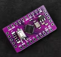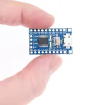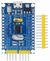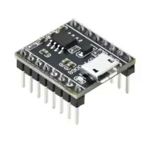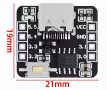
STC8G1K08A 51 MCU Development Board with ADC
= Microcontroller Module with ADC Function for 51 Projects =
The STC8G1K08A is a highspeed 1T 8051 microcontroller with builtin ADC function, ideal for compact DIY projects. Operating at 1.9V to 5.5V, it offers 6 channels of ADC input for sensor and voltage monitoring applications .
Enhanced 8051 Core - Up to 12x faster than traditional 8051
6Channel ADC Multiple analog inputs for versatile sensing
Ensure your chip is STC8G1K08A (with "A" suffix) the nonA version has no ADC
Use P3.2 or P5.4/P5.5 pins for ADC input on the 8-pin package
P3.0 and P3.1 are typically used for serial communication and programming
= Technical Specifications =
| Parameter | Value |
|---|
| Core | 1T 8051 (STC8G series) |
| Speed | Up to 12x faster than standard 8051 |
| Flash Memory | 8KB |
| Operating Voltage | 1.9V to 5.5V |
| ADC Channels | 6 (all I/O pins on 8-pin package) |
| ADC Resolution | 10-bit (configurable) |
| Package Options | SOP8, DFN8, SOP16, SOP20 |
= Key Features =
Integrated ADC 6 channels with 10bit resolution
Wide Voltage Range - 1.9V to 5.5V operation
HighSpeed Core 1T architecture for fast execution
Flexible I/O - All pins configurable as ADC inputs
Internal Reference - 1.19V bandgap for accurate measurements
No External Crystal Needed Builtin oscillator
== Applications ==
- Battery voltage monitoring
- Sensor data acquisition
- Simple IoT devices
- LED and display control
- Educational microcontroller projects
CostEffective ~$0.70 per chip for ADC capability
Simple Programming - Compatible with standard 51 tools
√ Works with Keil and STC-ISP programming tools
√ Ideal for battery-powered projects
√ Widely supported by online resources
= ADC Configuration Guide =
Setting up ADC on the STC8G1K08A requires careful configuration of several registers :
- ADC_CONTR: Enable ADC and select channel
- ADCCFG: Configure data format and clock speed
- ADCTIM: Set internal ADC timing (requires P_SW2 access)
- PxM0/PxM1: Set ADC pins to high-impedance mode
Set ADC pin to high-impedance input mode for accurate readings
Use ADC channel 15 to measure internal 1.19V reference for voltage calibration
The "STC8G1K08" (no "A") has no ADC - always check your chip marking
= Programming Notes =
The ADC on the STC8G1K08A uses a SAR architecture that requires proper register configuration before conversion. Initialization steps include enabling ADC power, selecting the channel, and configuring timing registers .
For multiple ADC channels:
- Configure pins to high-impedance input mode
- Select channel via ADC_CONTR register
- Sample sequentially (polling or interrupt method)
- Use averaging for noise reduction
Simple Polling Method - Wait for ADC flag to complete
Interrupt Support - ADC can trigger interrupts on completion
Supports both leftaligned and rightaligned ADC results
Internal bandgap reference enables accurate voltage measurement
√ Sample code available in STC datasheets
√ Compatible with STC-ISP and Keil development tools
= Troubleshooting =
ADC reads zero:
- Verify chip is STC8G1K08A (check chip marking)
- Set ADC pin to high-impedance mode
- Avoid using P3.0/P3.1 for ADC if using serial
ADC flag not setting:
- Check ADC_CONTR register settings
- Ensure ADC power is enabled
- Try polling method with adequate delay
- Some batches may require alternative approach