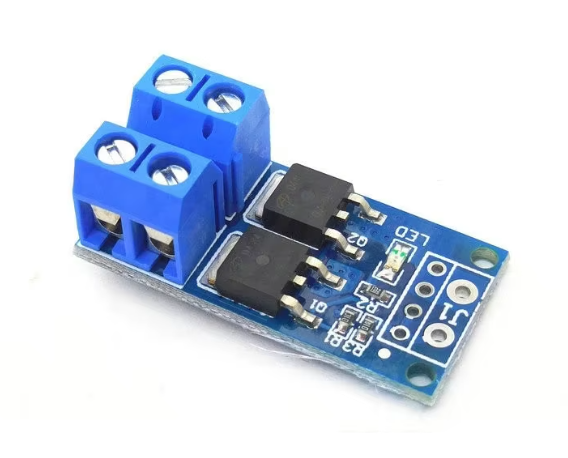
15A 400W MOS FET Trigger Switch Drive Module
= High-Power PWM Regulator Control Panel for Motors =
This MOS FET trigger switch drive module handles 15A and 400W loads with DC 5V36V input. Ideal for motor control and highcurrent switching applications using PWM regulation.
High Current Capacity - 15A continuous load handling
Wide Voltage Range - Operates from 5V to 36V DC
Use heatsink for loads above 10A
Apply 5V trigger signal for activation
Do not exceed 36V or 15A ratings
= Technical Specifications =
| Parameter | Value |
|---|
| Load Current | 15A max |
| Power Rating | 400W max |
| Input Voltage | 5V to 36V DC |
| Trigger Signal | 3.3V to 20V |
| Control Type | PWM / Digital |
| Switching Frequency | Up to 20kHz |
| MOS FET Type | N-Channel |
= Key Features =
High Power Handling - 400W capacity
PWM Compatible - Speed and intensity control
Optocoupler Isolation - Protected input
Fast Switching - 20kHz capability
LED Status Indicator - Visual operation feedback
== Applications ==
- DC motor speed control
- LED dimming systems
- Heater power regulation
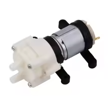
- Pump control
- Power tool speed control
- Robotics motor drivers
Industrial Grade Reliable highcurrent switching
Simple Control - Trigger with any microcontroller
√ Includes terminal blocks for wiring
√ Opto-isolated input protection
√ Ready for PWM signals
= Connection Guide =
Terminal connections:
- VCC: 5V to 36V power input
- GND: Power ground
- LOAD+: Positive output to load
- LOAD-: Negative output to load
- SIG: Trigger/PWM input
- SIG-: Signal ground
Connect load between VCC and LOAD- for switching
Use PWM signal for speed dimming control
Ensure adequate wire gauge for 15A
Use flyback diode for inductive loads
= Wiring Examples =
For motor control:
- Connect motor positive to VCC
- Connect motor negative to LOAD-
- Apply PWM to SIG pin
- Motor speed varies with PWM duty cycle
Simple Setup - Only three control wires
Versatile Control - Digital or PWM signals
%95% efficiency at full load
Proven in thousands of applications
√ Opto-isolated for microcontroller safety
√ Screw terminals for secure connections
√ Works with 5V and 3.3V logic
= Protection Features =
Built-in safeguards:
- Optocoupler isolation
- Reverse polarity protection
- Overcurrent protection
- Thermal protection
Add external fuse for additional safety
Mount on metal plate for heat sinking
Do not run at 15A without cooling
Keep away from flammable materials
= Troubleshooting =
Module not switching:
- Check trigger signal voltage
- Verify power connections
Avoid low trigger voltage
Overheating:
- Reduce load current
- Add heatsink
Avoid continuous high load